 Sign up with Google
 Sign in with Zoho


Diagram of a Muffle Furnace: The Elements Behind Heat-Treatment Technology

Those preparing for an exam in materials science or trying to figure out equipment in a laboratory setting have likely found themselves referencing a muffle furnace diagram at least once, attempting to grasp the mechanics behind generating and controlling heat without ever actually handling the sample in question. Learning about a muffle furnace diagram is more than just an exercise in learning theory; it can help to diagnose problems and understand why some of its elements are important.
Why a Muffle Furnace Diagram Is Important Outside the Lecture Hall
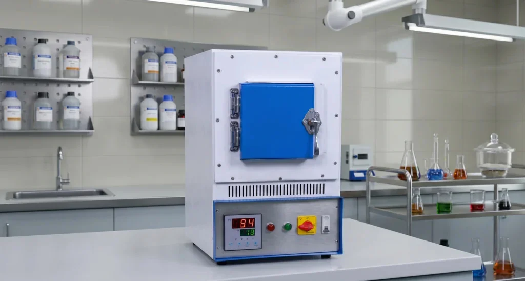
A muffle furnace diagram details the structure that sets it apart from basic ovens or other heating systems. One look at a muffle furnace diagram will show why samples inside the furnace remain uncontaminated even when they are heated to very high temperatures — the key feature of a muffle furnace is that it completely separates the heat source from the sample itself.
Main Components Highlighted in a Common Diagram
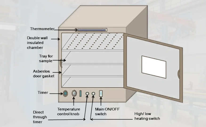
The diagram for any muffle furnace always shows the outer shell made up of either mild steel or stainless steel. This is because the outer shell encloses the internal insulating layer that helps to protect the people from being heated externally. Within the outer shell lies the insulating layer, which is usually made up of either ceramic fiber or firebrick. The insulating layer holds in the heat inside the chamber, while the outer shell stays cool. Lastly, the heating elements are always found within the chamber walls and not inside the sample.
The Chamber and Temperature Sensing System
In a muffle furnace diagram, the focus always falls on the muffle chamber, which is an isolated compartment where crucibles and other samples are set. The muffle chamber communicates with the thermocouple, which measures the temperature within the chamber and transmits the information to the digital controller located on the outside of the furnace. The digital controller then analyzes the thermocouple reading and controls the power input into the heating elements based on the readings. A properly drawn muffle furnace diagram should show this process because it helps understand why calibration problems lead to inaccurate temperatures.
Ventilation and Safety Aspects Usually Ignored
When observing the muffle furnace diagram, people tend to concentrate only on the heating component of the process and completely ignore the ventilation hole, which is a small hole that helps the gases generated by sample burning to escape without increasing the pressure in the sealed enclosure. The safety interlock mechanism is another feature that can be found in a more elaborate furnace diagram; it ensures that the door cannot be opened when the furnace is still too hot, thus preventing any risk of burns.
Application of this Knowledge in the Laboratory
Knowledge of each part of a muffle furnace diagram simplifies the troubleshooting process if any problems arise with the equipment. Unstable heating is usually caused by the position of the heating elements or insulation, but only when one is aware of the diagram of the device can he/she recognize this problem. Abnormal temperature readings are caused by the location of the thermocouples or their calibration, but once again, one will be able to identify the cause of this malfunction after examining the diagram.
Conclusion
The study of a muffle furnace diagram is not just an exercise that can help students satisfy their curiosity. In reality, a diagram is very helpful for understanding how controlled and contaminant-free heating at high temperatures operates.