 Sign up with Google
 Sign in with Zoho

A reliable digital system starts with reliable timing. Whether a circuit is built for communication, automation, computing, measurement, or signal processing, each device on the board depends on a clock signal to perform its task at the correct moment. When that timing becomes unstable, delayed, noisy, or poorly distributed, the system can face data errors, synchronisation issues, and reduced performance. PLL Clock Buffers are designed to solve these challenges by delivering controlled, stable, and well-aligned clock signals across modern electronic systems.
PLL Clock Buffers are more than simple distribution devices. They use phase-locked loop technology to follow a reference clock and generate outputs that are phase-aligned, frequency-controlled, and suitable for demanding applications. This makes them valuable in designs where timing accuracy is not optional but essential.
Why Do Modern Circuits Need PLL Clock Buffers?
Older and simpler circuits may use a single timing source with basic routing. However, today’s electronic designs often contain multiple ICs, high-speed interfaces, processors, memory devices, converters, and communication modules. Each of these parts may need a stable clock signal, and sending one raw signal across the entire board can create problems.
A PLL Clock Buffer helps overcome these problems by taking one reference clock and distributing multiple clean outputs. This reduces the burden on the original source and allows different sections of the system to receive dependable timing.
Modern circuits need PLL Clock Buffers because they help support:
- High-speed data transfer
- Multi-chip synchronisation
- Stable frequency generation
- Reduced timing uncertainty
- Better signal quality over PCB traces
- Cleaner delivery to sensitive components
How Does a PLL Clock Buffer Control Timing?
The phase-locked loop inside the buffer continuously compares the output timing with the reference input. When there is a phase or frequency difference, the loop adjusts its internal control system until the output is locked to the reference. This locking process allows the buffer to maintain a stable relationship between input and output signals.
Once locked, the device can distribute timing signals with improved control. Depending on the part, it may also create different frequencies using multiplication or division. This is useful when one system needs several related speeds from a single reference source.
The result is a more organised timing structure where connected devices operate from a controlled network instead of independent or unstable timing paths.
What Problems Can PLL Clock Buffers Help Prevent?
Timing problems can be difficult to diagnose because they often appear as random system faults. A board may work during testing but fail under temperature change, higher speed, or heavier data load. PLL Clock Buffers help reduce the risk of these issues by improving the quality and distribution of the clock signal.
They can help prevent:
- Data transfer errors caused by unstable signal edges
- Timing mismatch between processors, FPGAs, and interface ICs
- Excessive loading on an oscillator or clock generator
- Signal weakening across long or complex PCB routes
- Unwanted delay differences between output channels
- Frequency drift that affects stable operation
By improving the timing foundation, PLL Clock Buffers make the overall design more dependable.
Where Do PLL Clock Buffers Fit in a Clock Tree?
In a clock tree, the reference signal begins from a source such as an oscillator, clock generator, timing module, or processor output. From there, the signal must be delivered to different devices. A PLL Clock Buffer is commonly placed between the source and the destination components to manage this distribution.
It acts as a central timing hub that receives, conditions, and distributes the signal. In advanced systems, several PLL Clock Buffers may be used to create different branches for separate functional areas, such as processing, communication, memory, and data conversion.
This approach gives designers more control over timing paths and helps keep important signals clean.
Which Specifications Matter Most in PLL Clock Buffers?
Choosing the correct PLL Clock Buffer requires more than matching the frequency. Engineers must compare several specifications to ensure the device fits the application.
Important specifications include:
- Input and output frequency range
- Number of available output channels
- Output logic format
- Additive jitter performance
- Phase noise characteristics
- Output-to-output skew
- Supply voltage range
- Power consumption
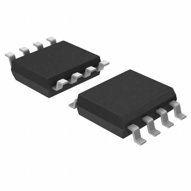
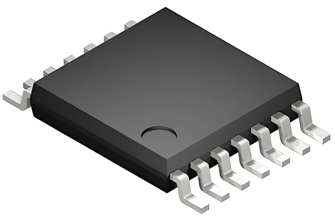
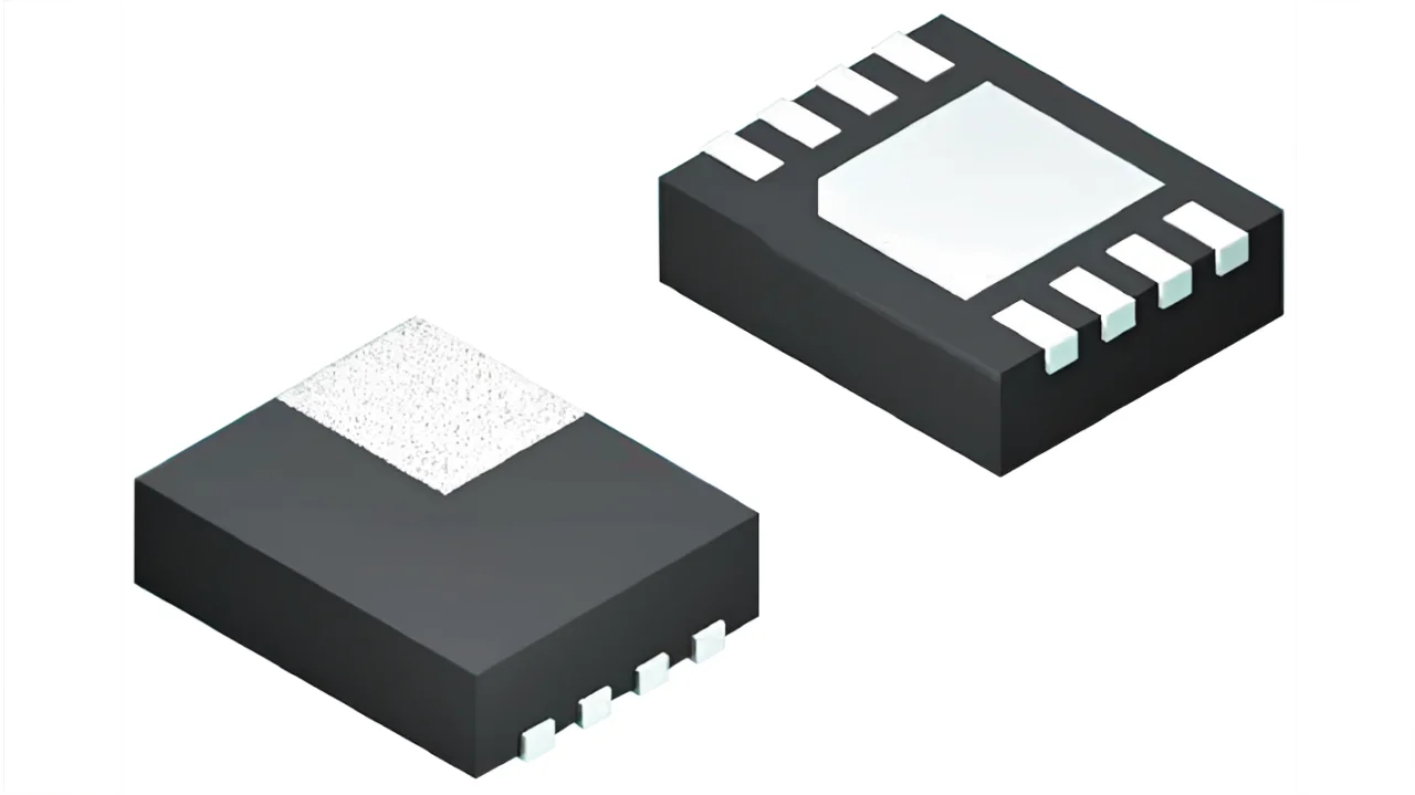
- Package type and pin layout
- Industrial or commercial temperature rating
- Frequency multiplication and division options
- Enable, reset, and configuration features
Output format is especially important. Some systems need CMOS outputs, while others require differential standards such as LVDS, LVPECL, HCSL, or CML. Selecting the wrong format can create compatibility problems or poor signal quality.
Why Is Jitter Performance Important?
Jitter is one of the most critical performance factors in PLL Clock Buffers. It represents small timing variations in the signal edge. In high-speed systems, these variations can reduce timing margin and increase the chance of incorrect data sampling.
Low jitter is especially important in:
- Ethernet and networking hardware
- RF and wireless communication
- High-speed ADC and DAC circuits
- PCIe and serial communication links
- FPGA timing systems
- Test and measurement equipment
A low-jitter PLL Clock Buffer helps preserve signal accuracy and allows high-speed data paths to operate more reliably.
How Does Skew Affect Multi-Output Designs?
Skew is the timing difference between two or more outputs. In systems where several devices must act at nearly the same time, excessive skew can cause synchronisation failure.
For example, when one device receives a signal edge earlier than another, data may be captured before it is ready or after it has changed. A PLL Clock Buffer with low output skew helps keep all outputs closely aligned, improving coordination across the circuit.
This is useful in FPGA boards, memory systems, communication modules, and any design where several chips depend on the same timing reference.
How Can PCB Layout Improve PLL Clock Buffer Performance?
Even a high-quality PLL Clock Buffer can perform poorly if the PCB layout is not designed correctly. Timing signals are sensitive to noise, impedance mismatch, and routing imbalance. Good layout practice helps preserve the benefits of the device.
Designers should consider:
- Keeping traces short and controlled
- Matching trace lengths where alignment is important
- Using proper termination for high-speed outputs
- Placing decoupling capacitors close to power pins
- Separating noisy power or switching signals from timing paths
- Following the manufacturer’s layout guidance
- Maintaining clean ground and power planes
Good PCB design works together with the PLL Clock Buffer to create a stronger and more stable timing network.
What Applications Depend on PLL Clock Buffers?
PLL Clock Buffers are used wherever reliable timing is required. They are common in performance-focused systems that cannot tolerate unstable signals or large timing errors.
Typical applications include:
- Telecom infrastructure
- Network routers and switches
- Embedded computing boards
- FPGA and ASIC platforms
- Industrial control equipment
- Video processing systems
- Data acquisition hardware
- Automotive electronic modules
- Medical instruments
- Server and storage systems
- Wireless base stations
In these systems, timing quality directly affects speed, accuracy, and reliability.
Conclusion
PLL Clock Buffers are essential components for building stable and high-performance timing networks. They help distribute signals cleanly, reduce jitter, control skew, support multiple outputs, and improve synchronisation across complex electronic designs. By combining phase-locked loop control with buffering, they give engineers the flexibility needed to manage demanding timing requirements.
For modern circuits that involve high-speed data, multiple ICs, precise sampling, or communication interfaces, the right PLL Clock Buffer can improve signal integrity and system dependability. As electronics continue to become faster and more compact, accurate clock management will remain a key part of successful circuit design.