 Sign up with Google
 Sign in with Zoho

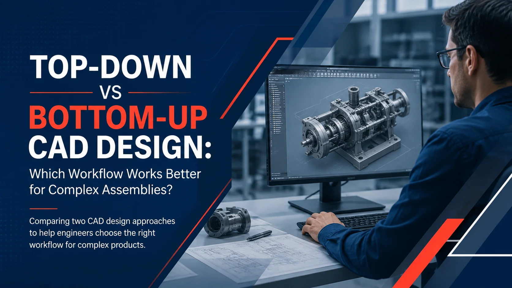
For complex mechanical assemblies, the choice between top-down and bottom-up CAD design can affect model stability, collaboration, change management, and engineering efficiency. Product development solutions increasingly need to accommodate both workflows because modern products combine tightly integrated custom components with standardized, supplier-provided, and reusable parts. Top-down design establishes the overall product architecture first and uses it to drive component development, while bottom-up design creates individual parts before assembling them. For most complex products, the practical answer is not choosing one exclusively, it is determining where each workflow provides the strongest engineering control.
Key Takeaways
- Top-down CAD starts with product-level architecture, interfaces, and design intent.
- Bottom-up CAD starts with individual parts or subassemblies and builds toward the finished product.
- Top-down is generally better for tightly coupled, frequently changing assemblies.
- Bottom-up is effective for standardized, reusable, independently developed, or purchased components.
- A hybrid workflow can separate system-level dependencies from independent component design.
What Is Top-Down CAD Design?
Top-down CAD design begins with the overall assembly or product architecture and progressively defines its components. Engineers establish high-level relationships such as spatial constraints, interfaces, envelopes, mechanisms, and major dimensions before detailed component geometry is developed.
This approach is particularly useful when the geometry of one component depends heavily on another. For example, changing the envelope of an industrial machine may require corresponding changes to brackets, housings, shafts, panels, or cable-routing provisions.
Modern CAD platforms can support this approach through mechanisms such as shared parameters, master layouts, skeleton models, and in-context component design. PTC's documentation describes top-down design in Creo as starting with the finished product and working downward through assemblies, subassemblies, components, and their relationships.
The important concept is design intent: the model should capture why components relate to one another, not simply what their geometry looks like.
What Is Bottom-Up CAD Design?
Bottom-up CAD design begins with individual components and combines them into progressively larger assemblies. Each part is generally modeled as an independent design before being positioned and constrained within an assembly.
This workflow is well suited to products containing established or relatively independent components. Standard fasteners, bearings, motors, sensors, purchased components, and validated internal parts can often be developed or selected without requiring a master product model to control their geometry.
PTC identifies bottom-up design as a conventional assembly approach in which component-level designs are developed first and then incorporated into higher-level assemblies.
The primary advantage is component independence. Engineers can reuse existing parts and allow different teams to work on components without creating unnecessary relationships to the complete assembly.
Which Workflow Is Better for Complex Assemblies?
There is no universal winner. Top-down is generally stronger when component relationships and system-level changes dominate; bottom-up is stronger when components are independent and reusable.
Autodesk similarly describes top-down modeling as particularly suitable for complex or bespoke systems requiring global control, while bottom-up modeling works well when component relationships are standardized and already understood.
A useful decision framework is to assess four characteristics:
High dependency + high change frequency → Top-down
Low dependency + high reuse → Bottom-up
Mixed dependency + mixed component types → Hybrid
Multiple teams + complex interfaces → Controlled top-down architecture
This is more useful than selecting a workflow simply because an assembly contains a large number of components.
When Should Engineers Prefer Top-Down Design?
Top-down design becomes valuable when the product architecture determines component geometry.
Typical examples include:
- Automotive systems with tightly packaged components
- Aerospace structures with controlled interfaces and space claims
- Industrial machinery with coordinated mechanisms
- Medical devices with strict packaging requirements
- Complex electromechanical products
- Customized equipment produced in multiple configurations
Creo, for example, supports top-down methodologies using assembly-level design information and skeleton models. PTC describes skeleton models as mechanisms for communicating design information such as interfaces and space claims to downstream components.
The major benefit is controlled propagation of design intent. If an interface or major packaging requirement changes, associated component designs can respond to that higher-level definition rather than relying entirely on manual coordination.
However, top-down modeling introduces a trade-off: more relationships mean more governance responsibility. Poorly managed references can make models difficult to maintain.
When Does Bottom-Up Work Better?
Bottom-up design is often preferable when components have stable interfaces and independent ownership.
Suppose a machine uses a standard gearbox, commercially available motor, catalog bearings, fasteners, and an internally developed frame. There is little engineering value in making every purchased component dependent on the machine's master geometry.
Bottom-up modeling allows the existing components to remain independent while the assembly defines their placement and relationships.
This approach can also support reuse. A validated component can be incorporated into multiple product configurations without rebuilding its geometry for every project.
The limitation appears when supposedly independent parts actually have strong geometric dependencies. If engineers must repeatedly modify multiple components manually whenever one interface changes, the workflow may be creating avoidable coordination work.
Why Hybrid CAD Workflows Often Make More Sense
Complex assemblies frequently contain both system-driven and independent components. That makes hybrid modeling a practical alternative.
Autodesk explicitly supports workflows that combine top-down and bottom-up techniques, including top-down methods for custom subassemblies and bottom-up assembly of standardized or library components.
Consider a robotic production cell. Engineers might use top-down modeling to define the cell envelope, robot reach, tooling interfaces, guarding, and mounting locations. Individual motors, fasteners, sensors, purchased actuators, and reusable tooling could then remain bottom-up components.
The result is a deliberate dependency structure:
Product architecture → controlled custom geometry → independent reusable components
This prevents the opposite problems of excessive dependency and excessive manual coordination.
A Practical Framework for Choosing the Workflow
Before starting a complex assembly, engineering teams can ask:
1. What drives the geometry? If system-level interfaces drive most component geometry, start top-down.
2. How often will those relationships change? Frequent architectural changes increase the value of controlled associativity.
3. Which components already exist? Standard and validated components generally favor bottom-up reuse.
4. Who owns the design? Distributed teams need clear boundaries around references, interfaces, and component ownership.
5. What happens when the architecture changes? Test whether a major interface modification can propagate predictably without creating unstable dependencies.
This last question is frequently overlooked. A CAD workflow should be evaluated not only by how efficiently it creates the first version of an assembly, but by how safely it handles the tenth engineering change.
How CAD Strategy Fits Broader Product Development
CAD methodology increasingly sits within a larger digital engineering environment involving PLM, simulation, manufacturing, configuration management, and software. Consequently, product development solutions should preserve meaningful relationships between engineering decisions and downstream product information.
Organizations evaluating digital transformation services companies or digital transformation consulting services and solutions should therefore consider workflow architecture alongside software capabilities. Similarly, software engineering solutions may need to integrate with product data environments as physical products become increasingly connected and software-defined.
The objective is not to maximize automation or associative relationships. It is to establish appropriate control over the relationships that matter while preserving independence where independence improves reuse and maintainability.
Conclusion
Top-down and bottom-up CAD workflows solve different engineering problems. Top-down design is most effective when product architecture, interfaces, packaging, and design intent drive component geometry. Bottom-up design is most effective when parts are independent, standardized, reusable, or externally supplied.
For complex assemblies, a hybrid strategy often provides the strongest balance. The engineering team can control critical system-level relationships from the top while allowing stable components to remain independently managed.
The right product development solutions therefore begin with the product's dependency structure, not with a blanket preference for one modeling methodology.
FAQs
Is top-down CAD better for large assemblies?
Not necessarily. Top-down CAD can be advantageous for large assemblies with complex interdependencies, but assembly size alone does not determine the best workflow. A large product built largely from standardized components may work effectively with bottom-up or hybrid modeling.
What is the main advantage of bottom-up CAD?
The main advantage is component independence. Engineers can create, validate, reuse, and manage individual parts or subassemblies without requiring them to depend heavily on the overall product architecture.
Can Creo support top-down and bottom-up design?
Yes. Creo supports both approaches, including top-down methodologies involving assembly-level design information and skeleton models. PTC also documents simplified representations and assembly techniques applicable to both top-down and bottom-up workflows.
What is a hybrid CAD workflow?
A hybrid workflow combines top-down and bottom-up techniques within the same product. System-critical custom components can be driven from higher-level architecture, while standard, purchased, or reusable components remain independently modeled and assembled.
What is the biggest risk of top-down modeling?
Excessive dependency is a key risk. If too many components reference higher-level geometry without clear ownership and governance, seemingly simple design changes can create unexpected downstream effects and make the model harder to maintain.