 Sign up with Google
 Sign in with Zoho
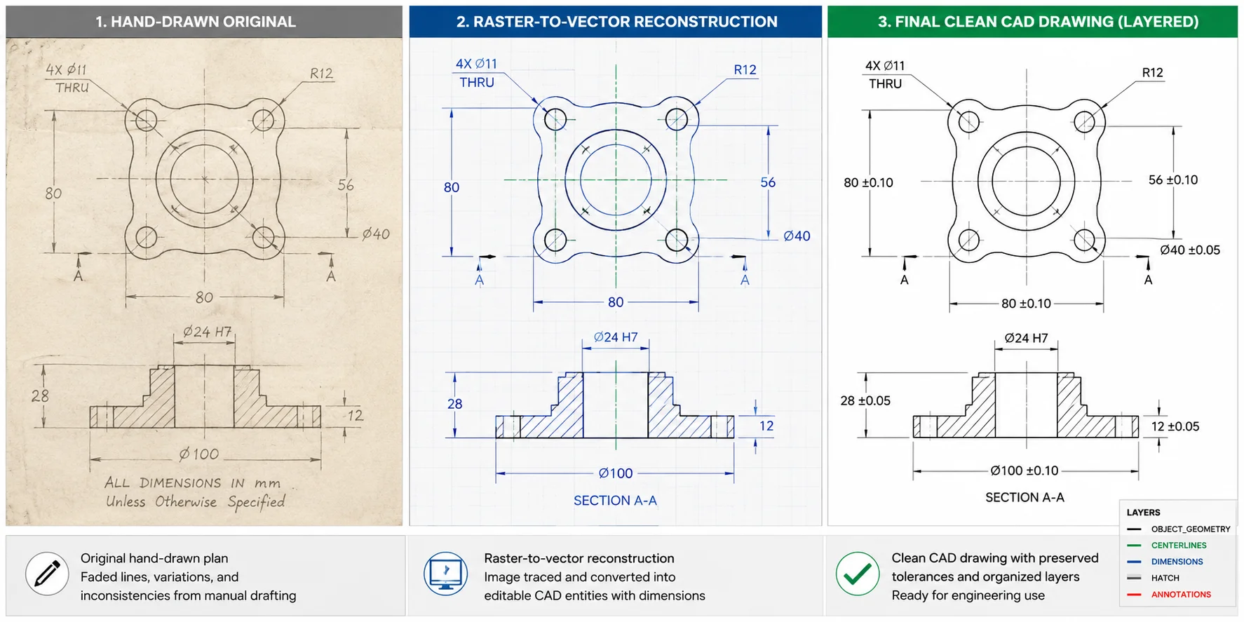
A hand-drawn engineering plan can contain far more information than its lines and dimensions suggest. A faint centerline may establish symmetry. A handwritten tolerance may determine whether two parts can assemble. A revision note in the margin may override an earlier dimension. When that drawing is digitized, the challenge is therefore not simply to make the sketch look clean on a computer screen. The real task is to preserve the engineering meaning behind it.
This distinction becomes especially important when old drawings are being converted for manufacturing, fabrication, inspection, renovation, or future design changes. A technically attractive CAD file can still be wrong if its geometry, dimensions, annotations, or design intent have been interpreted incorrectly.
Why digitizing an engineering drawing is more than tracing
Raster images and scans represent a drawing as pixels. CAD represents geometry as structured objects such as lines, arcs, circles, polylines, dimensions, text, and sometimes fully defined 3D features.
That difference creates several opportunities for error.
A scanned circle, for example, may appear slightly elliptical because of paper distortion or scanning. A straight line can contain small deviations caused by the original drafting instrument, printing, folding, or image resolution. Automatic vectorization can reproduce those imperfections unless the conversion process includes appropriate cleanup and interpretation.
Modern CAD tools can assist with this work. Autodesk's Raster Design documentation describes vectorization tools for converting raster geometry into CAD objects and includes methods for tracing lines, polylines, circles, arcs, and text. It also provides tools for checking and adjusting dimensions during vectorization.
But automation does not eliminate engineering judgment. A conversion specialist still needs to distinguish between an actual design feature and an artifact of the scanned source.
Start with the source, not the software
Before tracing anything, examine the original drawing as an engineering document.
Look for:
- Drawing number and revision
- Units and scale
- Title-block information
- General tolerances
- Datum references
- Section and detail views
- Centerlines and construction geometry
- Material notes
- Surface-finish symbols
- Welding or fabrication notes
- Handwritten changes
- Superseded dimensions
- References to other drawings
- Missing or ambiguous information
This initial review can reveal conflicts that are invisible when the drawing is treated merely as an image.
For example, suppose a scanned mechanical drawing contains a dimension of 50 mm, while a nearby handwritten revision changes it to 52 mm. A tracing workflow that follows the most visually prominent dimension could create a precise-looking but incorrect CAD model. The correct response is not to guess. The conflicting information should be resolved against the revision history, related documentation, or the responsible engineer.
The principle is simple: digitize the design information, not merely the ink.
Preserve dimensional intent before improving geometry
One of the most tempting steps in conversion is to "clean up" geometry. This can be useful, but it can also change the design.
Imagine a hand-drawn rectangular opening whose four corners are visibly imperfect. If the drawing's dimensions clearly establish equal opposite sides and perpendicular corners, rebuilding it as an exact rectangle may faithfully represent the intended design. On the other hand, if those irregularities represent a deliberately non-square feature, automatically regularizing them would introduce an error.
Dimensions, constraints, tolerances, and relationships should therefore guide geometric reconstruction.
This is particularly important for manufacturing drawings. NIST describes dimensions and tolerances as critical information for defining the shape requirements of manufactured parts.
A useful conversion workflow asks, feature by feature:
- What geometry is actually shown?
- What dimensions define it?
- Which dimensions have tolerances?
- Which features are related to datums?
- Is the visible geometry consistent with the stated dimensions?
- Is any discrepancy caused by the original drawing or by scanning?
- Does the source contain enough information to resolve the discrepancy?
If the source cannot answer a question, the CAD operator should flag it rather than silently inventing an answer.
Tolerances are design information, not decoration
A common mistake in legacy drawing conversion is to focus heavily on nominal dimensions while treating tolerances as secondary notes.
That approach can be dangerous.
A dimension of 25 mm and a dimension of 25 ± 0.02 mm communicate very different manufacturing requirements. Likewise, a geometric tolerance can control the relationship between features in a way that cannot be understood from nominal dimensions alone.
ASME Y14.5 establishes rules, definitions, symbols, requirements, and recommended practices for stating and interpreting geometric dimensioning and tolerancing (GD&T). NIST likewise identifies GD&T as important for product definition and for downstream manufacturing and inspection processes.
During conversion, preserve:
- Basic and reference dimensions
- Plus/minus tolerances
- Limit dimensions
- Datum identifiers
- Feature-control frames
- Material-condition modifiers
- Surface requirements
- General tolerance notes
Do not replace an explicit tolerance with an assumed CAD precision. A CAD system may store geometry to many decimal places, but that numerical precision does not automatically represent the functional tolerance of the physical part.
When raster-to-vector conversion works well—and when it does not
Raster-to-vector conversion is particularly useful for drawings containing clean, high-contrast geometry. It can significantly reduce repetitive tracing work and produce editable CAD entities rather than leaving the drawing as an image underlay.
However, the quality of the source has a major influence on the result.
Autodesk notes that raster-vector workflows can use different tools for different entity types and that raster text can be recognized and converted into CAD text. The practical implication is that conversion should be treated as a hybrid process: automation where recognition is reliable, human verification where interpretation matters.
Use known dimensions to control scale
A drawing does not necessarily need to be physically scanned at a perfect scale to be recoverable.
Suppose a scanned drawing contains a clearly specified 100 mm dimension. If the corresponding measured distance in the image is inconsistent because of scanning or paper distortion, that known dimension can serve as a reference for reconstruction.
A simple scale relationship is:
CAD length = measured image length × reference CAD length / measured reference length
For example, if a known 100 mm feature measures 4,000 image units while another feature measures 2,000 image units, proportional scaling would place the second feature at 50 mm—assuming the source is not distorted locally.
That final qualification matters. Uniform scaling can correct an overall size mismatch, but it cannot necessarily correct paper stretching, perspective distortion, or localized deformation. Where distortion is significant, multiple reference points and engineering judgment may be necessary.
Decide whether 2D CAD or 3D reconstruction is appropriate
Not every hand-drawn plan should become a 3D model.
For fabrication layouts, architectural details, electrical documentation, or straightforward mechanical drawings, a carefully reconstructed 2D CAD file may be the most appropriate deliverable.
A 3D model becomes more valuable when the downstream task requires:
- Assembly visualization
- Interference checking
- CNC or CAM preparation
- Mass or volume calculations
- Design modification
- Simulation
- Parametric revisions
- Product-development integration
The important question is not "Can this drawing be modeled in 3D?" but "What information will the next stage of the workflow require?"
A 2D drawing converted accurately into editable geometry may be more useful than a hastily created 3D model whose assumptions are difficult to verify.
File format should match the next user's workflow
Interoperability should be considered before delivery, not after conversion.
DWG and DXF are common choices for 2D CAD workflows, while STEP is widely used for exchanging product data between CAD and other engineering systems. NIST describes STEP under ISO 10303 as a standard for product-data exchange and notes that its scope extends beyond simple geometric exchange.
For STEP specifically, NIST's current software documentation describes support for parts, assemblies, dimensions, tolerances, and Product and Manufacturing Information (PMI), depending on the data represented in the file.
A practical deliverable package might therefore include:
- Editable DWG for native 2D CAD work
- DXF when required by a downstream system
- STEP for appropriate 3D product-data exchange
- PDF for visual reference and approval
- A conversion notes document identifying assumptions or unresolved items
The exact combination should depend on the recipient's CAD/CAM, fabrication, inspection, or document-control workflow.
Revision control matters after conversion
Legacy drawings often become more valuable once they are editable—but editability introduces a new risk: uncontrolled changes.
A digitized drawing should retain enough information to identify its source and revision. If possible, record:
- Original drawing identifier
- Original revision
- Conversion date
- Source format
- Conversion method
- Major assumptions
- Unresolved discrepancies
- Person or team responsible for review
ASME's Y14 standards include Y14.35 for revision of engineering product-definition datasets and associated documents, illustrating the importance of controlled revision practices in engineering documentation.
The converted CAD file should not become a new "master" simply because it is cleaner than the paper original. Its status should be clear: converted reference, reviewed production drawing, preliminary reconstruction, or another defined state.
A quality check should compare meaning, not just appearance
Plotting the finished CAD file and visually comparing it with the scan is useful, but it is only one level of checking.
A stronger review has several layers.
Geometry check
Confirm that major lines, arcs, holes, profiles, sections, and repeated features correspond to the source.
Dimension check
Compare critical dimensions rather than relying on visual similarity. Verify units, scale, decimal placement, diameter symbols, radii, and tolerances.
Annotation check
Review notes, callouts, symbols, datums, material specifications, and revision information.
Relationship check
Look for design relationships such as symmetry, concentricity, equal spacing, alignment, and feature orientation.
Manufacturing check
Ask whether the resulting CAD data communicates what a fabricator, machinist, inspector, or installer needs to know.
This final step is particularly important because a drawing can be geometrically faithful yet operationally incomplete.
When outside conversion expertise is worthwhile
Simple plans can sometimes be digitized internally. More complicated legacy drawings can require a combination of CAD knowledge, drafting experience, and engineering interpretation.
For organizations comparing outside providers, it is useful to ask whether the workflow includes manual quality control rather than relying exclusively on automated vectorization. A service page such as accurate cad conversion service can provide additional context when evaluating CAD conversion options.
The most useful questions are practical:
- What source formats can be accepted?
- Can the provider preserve layers and editable entities?
- How are dimensions and tolerances verified?
- How are ambiguous features handled?
- Can the output be delivered in the required CAD format?
- Is a PDF comparison or review copy supplied?
- How are revisions documented?
- Who performs the final quality check?
The answers matter more than claims about speed or volume.
A practical checklist before approving the final CAD file
Before a digitized engineering drawing enters production or becomes part of a permanent document library, verify:
- Correct drawing number and revision
- Correct units
- Correct scale or calibrated reference dimensions
- All critical geometry reconstructed
- Dimensions checked against the source
- Tolerances preserved
- GD&T symbols and datums reviewed where applicable
- Notes and material information preserved
- Revision marks accounted for
- Layers organized logically
- Required file formats tested
- Ambiguities documented rather than guessed
- Final CAD output visually compared with the source
- Appropriate engineering or manufacturing review completed
The objective is not to produce the prettiest digital drawing. It is to produce a trustworthy engineering record.
The real measure of a successful conversion
Digitizing a hand-drawn engineering plan succeeds when the resulting CAD data preserves the information that makes the original drawing useful.
That means geometry must remain faithful, dimensions must retain their meaning, tolerances must survive the conversion, revisions must remain traceable, and ambiguous information must be treated honestly. Automation can accelerate the mechanical work, but engineering judgment remains essential wherever the source contains uncertainty.
A well-converted drawing should allow the next person in the workflow to work confidently without having to rediscover what the original drafter intended. That is ultimately what turns an old sheet of paper—or a scanned image—into useful digital engineering data.
Sources
- ASME Y14 Standards — Engineering drawing, dimensioning, tolerancing, and revision standards.
- NIST: Testing Implementations of GD&T in CAD Software — CAD implementation and downstream manufacturing/inspection context for GD&T.
- Autodesk Raster Design: Converting Raster Entities to Vector — Raster-to-vector tools and CAD entity conversion workflow.
- NIST: Introduction to ISO 10303 (STEP) — Product-data exchange and CAD interoperability.
- NIST: STEP File Analyzer and Viewer — STEP support for CAD geometry and product/manufacturing information.